Monday 3 August 2009

Chunk 48 - FINAL VERSION

Bringing it together 3
In this chunk we will continue on from the last by using the vertex function to create shapes. However, this time we will extend the animation to three-dimensional shapes. What we are attempting to draw is shown in figure 48.1 below
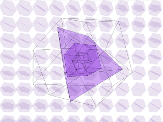
Figure 48.1 The final animation

This looks extraordinarily complex, so we will break it down into parts and explain how each part is done. As we have already drawn hexagons in the previous chunk, we will start with those, but we will alter the code so we can reuse it to create other shapes.

Each vertex in a polygon can be calculated using a formula related to the number of sides. Most polygons (that is 2D shapes) can be drawn using the same formula, so we will be able to reuse it to draw polygons with different numbers of sides. Using trigonometric functions, which we will describe in more detail later in the book, we can calculate each vertex by

x-coordinate = (coordinate + edge size * cos(current side index * 2 * PI / sides));
y-coordinate = (coordinate + edge size * sin(current side index * 2 * PI / sides));

We can use this to create a generic function for creating polygons by looping over these statements by the number of sides we want and drawing a vertex at the calculated coordinates.
 
/**
* Draw a 2D polygon with the given number of sides and size
* @param sides the number of sides
* @param size the size of one edge
*/
void draw2DPolygon(int sides, int size) {
// starting coordinates
int x = 0;
int y = 0;

// draw the polygon
beginShape();
// loop for the number of sides + 1 (so we join up the last side to the starting vertex)
for (int i = 0; i <= sides; i++) {
// work out the coordinates of the vertex
float xCoord = (x + size * cos(i * 2 * PI / sides));
float yCoord = (y + size * sin(i * 2 * PI / sides));
// plot the vertex
vertex(xCoord, yCoord);

}

endShape();

}

The centre point of the hexagon can be calculated in a similar way and the lines drawn from each vertex to the centre. What we need to do is work out the coordinates of each vertex, add them together, then divide this value by the number of sides. This will give us the centre-point coordinates of the shape. For example

for (int i = 0; i < sides; i++) {
// work out the coordinates
float xCoord = (x + size * cos(i * 2 * PI / sides));
float yCoord = (y + size * sin(i * 2 * PI / sides));
// add them all together
centreX += xCoord;
centreY += yCoord;

}
// calculate the centre coordinates
centreX = (centreX / sides) * -1;
centreY = (centreY / sides) * -1;

The code above will calculate the centre-point of the shape, and that point used as the basis for drawing the vertices that make up the sides. This will mean that, when we rotate it, the shape will rotate around its centre.

Although this initially seems like it is more complicated than the method seen in chunk 47, it is a much more generic way of creating the hexagon that means we can use it to create other polygons. This means we can easily draw a smaller pentagon simply by calling our function with different arguments. If we add a loop, similar to how we implemented the previous 'hexagon wave', we can create our background of rotating polygons.

// loop over the height of the screen
for (int i = hexagonSize; i < height + hexagonSize; i = i + (hexagonSize * 2)) {
// loop over the width of the screen
for (int j = hexagonSize; j < width; j = j + (hexagonSize * 2)) {

This time, however, we will create a background field of rotating hexagons and pentagons by drawing the pentagons on top of the hexagons, then rotating them in different directions. As we now have our function for creating polygons, all we need do is call it with the number of sides and size we want. The code now looks like the below

int hexagonSize = 40;
int pentagonSize = 30;

void setup() {

size(800, 600, P3D);

}

void draw() {

// define rotation direction variables
float clockwiseDirection = frameCount * PI;
float antiClockwiseDirection = frameCount * -PI;

background(255);

// loop over the height of the screen
for (int i = hexagonSize; i < height + hexagonSize; i = i + (hexagonSize * 2)) {
// loop over the width of the screen
for (int j = hexagonSize; j < width; j = j + (hexagonSize * 2)) {

pushMatrix();
translate(j, i, 0);
// hexagon
rotateZ(antiClockwiseDirection / 150);
rotateX(antiClockwiseDirection / 150);
rotateY(antiClockwiseDirection / 150);
draw2DPolygon(6, hexagonSize);
// pentagon
rotateZ(clockwiseDirection / 255);
rotateX(clockwiseDirection / 255);
rotateY(clockwiseDirection / 255);
draw2DPolygon(5, pentagonSize);

popMatrix();

}
}

}

/**
* Draw a 2D polygon with the given number of sides and size
* @param sides the number of sides
* @param size the size of one edge
*/
void draw2DPolygon(int sides, int size) {
// fill colour
fill(85, 26, 139, 30);
// line colour
stroke(138, 43, 226, 20);
// starting coordinates
int x = 0;
int y = 0;
// centre coordinates
float centreX = 0;
float centreY = 0;
// work out the centre coordinates using the coordinates of each vertex
for (int i = 0; i < sides; i++) {
// work out the coordinates
float xCoord = (x + size * cos(i * 2 * PI / sides));
float yCoord = (y + size * sin(i * 2 * PI / sides));
// add them all together
centreX += xCoord;
centreY += yCoord;

}
// calculate the centre coordinates
centreX = (centreX / sides) * -1;
centreY = (centreY / sides) * -1;
// draw the polygon
beginShape();
// loop for the number of sides + 1 (so we join up the last side to the starting vertex)
for (int i = 0; i <= sides; i++) {
// work out the coordinates of the vertex
float xCoord = (centreX + size * cos(i * 2 * PI / sides));
float yCoord = (centreY + size * sin(i * 2 * PI / sides));
// plot the vertex
vertex(xCoord, yCoord);

}

endShape();

}
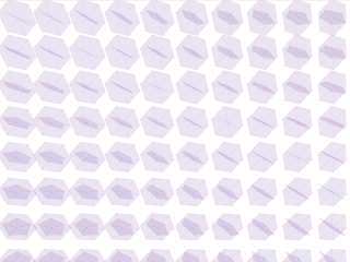

Figure 48.2 Background of rotating hexagons and pentagons

We can also do the same with the internal lines that we drew. As we have already calculated the centre-point, we can just draw a line from each vertex to the centre. This means it will work for both the hexagon and the pentagon.

// draw the internal lines
// loop for the number of sides
for (int i = 0; i < sides; i++) {
// work out the coordinates
float xCoord = (centreX + size * cos(i * 2 * PI / sides));
float yCoord = (centreY + size * sin(i * 2 * PI / sides));
// plot a line from the coordinate to the centre coordinates
line(xCoord, yCoord, centreX, centreY);

}

This function could be used, if we wished, to create any regular (that is, with equal side lengths) 2D polygon with 3 sides (triangle) or more. This makes the more complicated code we just created worth the effort because we don't need to keep creating functions every time we want a polygon with a different number of sides.

We can now look at drawing the 3D shapes which, as you might expect, are somewhat more complicated than 2D shapes, just as 2D shapes were more complicated than the 1D shapes (lines) you saw in chunk 46. Processing already has functions for some 3D shapes such as cubes and spheres, so we can utilise those for certain shapes. However, if we want a complicated shape, we will need to draw it ourselves using vertices, as we did with the 2D shapes. This time, though, we need to specify three coordinates for each vertex to plot it in three-dimensions. Processing's vertex function can have 2 or 3 arguments, so we will be using the 3 arguments required for 3D in the form

vertex(x, y, z);

where the x and y coordinates are the same as seen previously, and the z coordinate is the third dimension – positive values for z are directly 'out' of the screen, so negative values are 'into' the screen.
The shape we are going to draw is a cuboctahedron – a 24-sided polyhedron (a 3D shape made up of polygons) with faces made up of 8 triangles and 6 squares, as shown in figure 48.3
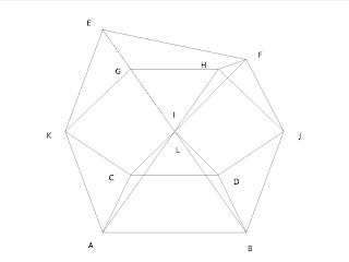
Figure 48.3 Cuboctahedron with vertices marked

In order to create some code that is readable, we will define each vertex in terms of the letters shown in figure 48.3. The simplest way to define a reusable shape is to create a class that defines how the shape is drawn. However, this is covered later in the book, so for now we will use an array and a switch statement – an array to define which points are drawn in which order, and a switch statement to draw the vertex in each element of the array.

The reason we are defining an array is because we need to draw the shape by drawing from one vertex to another without stopping – a little like trying to draw without taking your pen off the paper. This means that we end up drawing some of the lines more than once in order to reach the next vertex. The order we have determined, using the labelled points above, is:

A,I,E,K,A,B,J,F,I,B,D,L,H,J,D,C,K,G,L,C,A,I,E,G,H,F,E

We can create an array of these characters and use it in a switch statement to create the vertex for each associated point by using a for statement to loop over the elements in the array. We will therefore create a function that draws the vertices when given an array of points and an edge size for each line in the shape – this will allow us to create a cuboctahedron of any size we wish.

Firstly we need to calculate the size of one of the diagonals from the size of a straight edge. We won't explain this fully except to say that this is a standard calculation of the diagonal using Pythagoras theorem

// calculate the diagonal length
float halfEdgeSize = edgeSize / 2;
float halfDiagonalSize = (sqrt((sq(edgeSize)) + (sq(edgeSize)))) / 2;

We also need to draw the shape in relation to its centre point, so that it rotates around the centre. The centre point of our cuboctahedron is at point (0,0,-edgeSize) – that is one line-length into the screen – the half-way point between vertices I and L. If we draw our vertices in relation to these coordinates, the shape will be centred around that point and so rotate properly. We will loop over the points in our array and, using a switch statement, draw the corresponding vertex. Our code, then, will look like this

// define the centre point of the shape
float x = 0;
float y = 0;
float z = -edgeSize;

// loop over the array of vertices
for (int i = 0; i < vertices.length; i++) {
char vertex = vertices[i];
// draw the corresponding vertex
switch (vertex) {
case 'A':
vertex(x - halfEdgeSize, y - halfDiagonalSize, z + halfEdgeSize);
break;
case 'B':
vertex(x + halfEdgeSize, y - halfDiagonalSize, z + halfEdgeSize);
break;
case 'C':
vertex(x - halfEdgeSize, y - halfDiagonalSize, z + (halfEdgeSize * 3));
break;
case 'D':
vertex(x + halfEdgeSize, y - halfEdgeSize, z + (halfEdgeSize * 3));
break;
case 'E':
vertex(x - halfEdgeSize, y + halfEdgeSize, z + halfEdgeSize);
break;
case 'F':
vertex(x + halfEdgeSize, y + halfEdgeSize, z + halfEdgeSize);
break;
case 'G':
vertex(x - halfEdgeSize, y + halfDiagonalSize, z + (halfEdgeSize * 3));
break;
case 'H':
vertex(x + halfEdgeSize, y + halfDiagonalSize, z + (halfEdgeSize * 3));
break;
case 'I':
vertex(x, y, z);
break;
case 'J':
vertex(x + (halfEdgeSize * 2), y, z + (halfEdgeSize * 2));
break;
case 'K':
vertex(x - (halfEdgeSize * 2), y, z + (halfEdgeSize * 2));
break;
case 'L':
vertex(x, y, z + (halfEdgeSize * 4));
break;
}
}

We won't explain how each vertex was calculated – however, it is relatively easy if you have a basic knowledge of trigonometry. You may have noticed that there is no default case in our switch statement. This is deliberate as we only want to draw vertices for the point we have defined – there is no sensible default case we could create, so it can be omitted. We will call this function drawCuboctahedron()

void drawCuboctahedron(char[] vertices, float edgeSize) {

where vertices is the array we will create, and edgeSize is the size of one edge of the shape.
We now need to define the array that contains the order of the vertices we need to draw using the above code. We have already stated the order of the points, so this just needs to be converted into a character array and passed to the drawCuboctahedron() function we have just created

/**
* Draws a cuboctahedron of the given size
*
* @param size the edge size of the shape
*/
void cuboctahedron(int size) {
// define the array with the point ordering
char[] vertices = new char[] {
'A',
'I',
'E',
'K',
'A',
'B',
'J',
'F',
'I',
'B',
'D',
'L',
'H',
'J',
'D',
'C',
'K',
'G',
'L',
'C',
'A',
'I',
'E',
'G',
'H',
'F',
'E' };
// draw the shape
beginShape();
drawCuboctahedron(vertices, size);
endShape();

}

If we now call this cuboctahedron() function from the draw method, we will create our 3D shape. We can then add rotation functions to rotate the shape as shown below

pushMatrix();
// move to the centre of the screen
translate(width / 2, height / 2, 0);

// rotate in all 3 axes
rotateX(clockwiseDirection / 250);
rotateY(clockwiseDirection / 250);
rotateZ(clockwiseDirection / 250);
cuboctahedron(250);

popMatrix();

This will draw and rotate the cuboctahedron along all 3 axes as shown in figure 48.4. The parameters we have given to the rotate functions is defining how fast it should rotate and in which direction. In this case we have stipulated a clockwise direction. The /250 part is the speed, in this case we are dividing by 250, so the speed will be quite slow
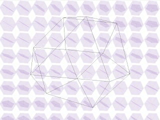
Figure 48.4 Cuboctahedron

The next shape in our animation is the pyramid shape – actually a 'triangular dipyramid', a 9-sided 6-faced polyhedron where the faces are all triangles. For this we are going to cheat and use one of Processing's built-in functions – oddly, the sphere() function. The sphere() function, as you would expect, creates a 3D sphere, with a parameter that defines the radius of the sphere. However, the resolution of the sphere can be altered using the sphereDetail() function. A spheres resolution is the number of faces that are used to display the sphere – the default is 30. Each face in the sphere is actually a triangle, so changing the resolution to 1 like this:

sphereDetail(1);
sphere(200);

will result in sphere with 6 sides – our triangular dipyramid. We can add some colour and some transparency so all the sides can be seen using the fill() function – colour and transparency is covered later in the book, so we won't explain here except to say that this is a semi-transparent purple colour

fill(138, 43, 226, 100);
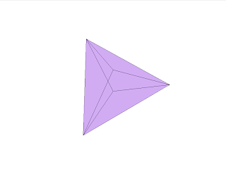


Figure 48.5 Triangular Dipyramid

We can now add this into our animation and rotate it slightly differently so that they appear to rotate inside each other, for example

rotateX(antiClockwiseDirection / 250);
rotateY(antiClockwiseDirection / 250);
rotateZ(antiClockwiseDirection / 250);
sphereDetail(1);
sphere(200);
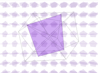


Figure 48.6 Triangular Dipyramid rotating inside a cuboctahedron

From here on most of the hard work has already been done for us. Our next shape is a cube which, fortunately, Processing already provides a function for in the form

box(size);

where the parameter is the size of the x, y and z dimensions, creating a cube (incidentally, you can provide different parameters for the 3 sides, which creates a non-square box). All we need do, therefore, is provide rotation function calls and create our box, easy!

rotateX(clockwiseDirection / 200);
rotateY(clockwiseDirection / 200);
rotateZ(clockwiseDirection / 200);
box(120);

This time we are rotating the box faster than the previous shapes which provides us with an interesting animation of having the shapes rotate in different directions and at different speeds
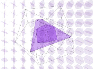
Figure 48.7 Cube inside a triangular dipyramid inside a cuboctahedron

The last shape we are going to animate, just to show that our code is reusable, is another, smaller cuboctahedron. Again, all we need to do is provide rotation function calls and create our cuboctahedron

rotateX(antiClockwiseDirection / 150);
rotateY(antiClockwiseDirection / 150);
rotateZ(antiClockwiseDirection / 150);
cuboctahedron(50);

This time a really small one rotating even faster, which finishes off our animation. The final code for creating the animation shown at the start, in figure 48.1, is as below

// sizes of the 2D shapes
int hexagonSize = 40;
int pentagonSize = 30;

void setup() {

size(800, 600, P3D);

}

void draw() {

// define rotation direction variables
float clockwiseDirection = frameCount * PI;
float antiClockwiseDirection = frameCount * -PI;
// reset the bakcground
background(255);
// fill the shapes with a purpley-colour
fill(138, 43, 226, 100);

pushMatrix();
// move to the centre of the screen
translate(width / 2, height / 2, 0);
// cuboctahedron
rotateX(clockwiseDirection / 250);
rotateY(clockwiseDirection / 250);
rotateZ(clockwiseDirection / 250);
cuboctahedron(250);
// triangular dipyramid
rotateX(antiClockwiseDirection / 250);
rotateY(antiClockwiseDirection / 250);
rotateZ(antiClockwiseDirection / 250);
sphereDetail(1);
sphere(200);
// cube
rotateX(clockwiseDirection / 200);
rotateY(clockwiseDirection / 200);
rotateZ(clockwiseDirection / 200);
box(120);
// small cuboctahedron
rotateX(antiClockwiseDirection / 150);
rotateY(antiClockwiseDirection / 150);
rotateZ(antiClockwiseDirection / 150);
cuboctahedron(50);

popMatrix();

// loop over the height of the screen
for (int i = hexagonSize; i < height + hexagonSize; i = i + (hexagonSize * 2)) {
// loop over the width of the screen
for (int j = hexagonSize; j < width; j = j + (hexagonSize * 2)) {

pushMatrix();
translate(j, i, 0);
// hexagon
rotateZ(antiClockwiseDirection / 150);
rotateX(antiClockwiseDirection / 150);
rotateY(antiClockwiseDirection / 150);
draw2DPolygon(6, hexagonSize);
// pentagon
rotateZ(clockwiseDirection / 255);
rotateX(clockwiseDirection / 255);
rotateY(clockwiseDirection / 255);
draw2DPolygon(5, pentagonSize);

popMatrix();

}
}

}

/**
* Draw a 2D polygon with the given number of sides and size
* @param sides the number of sides
* @param size the size of one edge
*/
void draw2DPolygon(int sides, int size) {
// fill colour
fill(85, 26, 139, 30);
// line colour
stroke(138, 43, 226, 20);
// starting coordinates
int x = 0;
int y = 0;
// centre coordinates
float centreX = 0;
float centreY = 0;
// work out the centre coordinates using the coordinates of each vertex
for (int i = 0; i < sides; i++) {
// work out the coordinates
float xCoord = (x + size * cos(i * 2 * PI / sides));
float yCoord = (y + size * sin(i * 2 * PI / sides));
// add them all together
centreX += xCoord;
centreY += yCoord;

}
// calculate the centre coordinates
centreX = (centreX / sides) * -1;
centreY = (centreY / sides) * -1;
// draw the polygon
beginShape();
// loop for the number of sides + 1 (so we join up the last side to the starting vertex)
for (int i = 0; i <= sides; i++) {
// work out the coordinates of the vertex
float xCoord = (centreX + size * cos(i * 2 * PI / sides));
float yCoord = (centreY + size * sin(i * 2 * PI / sides));
// plot the vertex
vertex(xCoord, yCoord);

}

endShape();
// draw the internal lines
// loop for the number of sides
for (int i = 0; i < sides; i++) {
// work out the coordinates
float xCoord = (centreX + size * cos(i * 2 * PI / sides));
float yCoord = (centreY + size * sin(i * 2 * PI / sides));
// plot a line from the coordinate to the centre coordinates
line(xCoord, yCoord, centreX, centreY);

}
// reset the stroke colour to black
stroke(0);

}

/**
* Draw a cuboctahedron of the given size
* @param size the size of the shape
*/
void cuboctahedron(int size) {
// define the vertices
char[] vertices = new char[] {
'A',
'I',
'E',
'K',
'A',
'B',
'J',
'F',
'I',
'B',
'D',
'L',
'H',
'J',
'D',
'C',
'K',
'G',
'L',
'C',
'A',
'I',
'E',
'G',
'H',
'F',
'E' };
// draw the shape
beginShape();
drawCuboctahedron(vertices, size);
endShape();

}

/**
* Draw the vertices for a cuboctahedron of the given size
* @param size the size of the shape
* @param vertices an array of vertex labels
*/
void drawCuboctahedron(char[] vertices, float edgeSize) {

// calculate the diagonal length
float halfEdgeSize = edgeSize / 2;
float halfDiagonalSize = (sqrt((sq(edgeSize)) + (sq(edgeSize)))) / 2;
// define the centre-point
float x = 0;
float y = 0;
float z = -edgeSize;
// loop over the array of vertices
for (int i = 0; i < vertices.length; i++) {
// extract the current vertex label
char vertex = vertices[i];
// draw the right one
switch (vertex) {
case 'A':
vertex(x - halfEdgeSize, y - halfDiagonalSize, z + halfEdgeSize);
break;
case 'B':
vertex(x + halfEdgeSize, y - halfDiagonalSize, z + halfEdgeSize);
break;
case 'C':
vertex(x - halfEdgeSize, y - halfDiagonalSize, z + (halfEdgeSize * 3));
break;
case 'D':
vertex(x + halfEdgeSize, y - halfEdgeSize, z + (halfEdgeSize * 3));
break;
case 'E':
vertex(x - halfEdgeSize, y + halfEdgeSize, z + halfEdgeSize);
break;
case 'F':
vertex(x + halfEdgeSize, y + halfEdgeSize, z + halfEdgeSize);
break;
case 'G':
vertex(x - halfEdgeSize, y + halfDiagonalSize, z + (halfEdgeSize * 3));
break;
case 'H':
vertex(x + halfEdgeSize, y + halfDiagonalSize, z + (halfEdgeSize * 3));
break;
case 'I':
vertex(x, y, z);
break;
case 'J':
vertex(x + (halfEdgeSize * 2), y, z + (halfEdgeSize * 2));
break;
case 'K':
vertex(x - (halfEdgeSize * 2), y, z + (halfEdgeSize * 2));
break;
case 'L':
vertex(x, y, z + (halfEdgeSize * 4));
break;
}
}

}


Hopefully this section has shown you that is it not as difficult as it looks to create exciting looking animations with Processings line and vertex functions, especially if you take it in small steps to build up your animation. These three 'bringing it together' chunks we have just covered should allow you to create interesting graphics and animations using shapes drawn in 1, 2 or 3 dimensions.

First 1000 words (draft)

Bringing it together 3
In this chunk we will continue on from the last by using the vertex function to create shapes. However, this time we will extend the animation to three-dimensional shapes. What we are attempting to draw is shown in figure 48.1 below

Figure 48.1 The final animation

This looks extraordinarily complex, so we will break it down into parts and explain how each part is done. As we have already drawn hexagons in the previous chunk, we will start with those, but we will alter the code so we can reuse it to create other shapes.

Each vertex in a polygon can be calculated using a formula related to the number of sides. Most polygons (that is 2D shapes) can be drawn using the same formula, so we will be able to reuse it to draw polygons with different numbers of sides. Using trigonometric functions, which we will describe in more detail later in the book, we can calculate each vertex by

x-coordinate = (coordinate + edge size * cos(current side index * 2 * PI / sides));
y-coordinate = (coordinate + edge size * sin(current side index * 2 * PI / sides));

We can use this to create a generic function for creating polygons

/**
* Draw a 2D polygon with the given number of sides and size
* @param sides the number of sides
* @param size the size of one edge
*/
void draw2DPolygon(int sides, int size) {
// starting coordinates
int x = 0;
int y = 0;

// draw the polygon
beginShape();
// loop for the number of sides + 1 (so we join up the last side to the starting vertex)
for (int i = 0; i <= sides; i++) {
// work out the coordinates of the vertex
float xCoord = (x + size * cos(i * 2 * PI / sides));
float yCoord = (y + size * sin(i * 2 * PI / sides));
// plot the vertex
vertex(xCoord, yCoord);

}

endShape();

}

The centre point of the hexagon can be calculated in a similar way and the lines drawn from each vertex to the centre. Although this initially seems like it is more complicated than the method seen in chunk 47, it is a much more generic way of creating the hexagon that means we can use it to create other polygons. This means we can easily draw a smaller pentagon simply by calling our function with different arguments. If we add a loop, similar to how we implemented the previous 'hexagon wave', we can create our background of rotating polygons. The code now looks like the below

int hexagonSize = 40;
int pentagonSize = 30;

void setup() {

size(800, 600, P3D);

}

void draw() {

// define rotation direction variables
float clockwiseDirection = frameCount * PI;
float antiClockwiseDirection = frameCount * -PI;

background(255);

// loop over the hieght of the screen
for (int i = hexagonSize; i < height + hexagonSize; i = i + (hexagonSize * 2)) {
// loop over the width of the screen
for (int j = hexagonSize; j < width; j = j + (hexagonSize * 2)) {

pushMatrix();
translate(j, i, 0);
// hexagon
rotateZ(antiClockwiseDirection / 150);
rotateX(antiClockwiseDirection / 150);
rotateY(antiClockwiseDirection / 150);
draw2DPolygon(6, hexagonSize);
// pentagon
rotateZ(clockwiseDirection / 255);
rotateX(clockwiseDirection / 255);
rotateY(clockwiseDirection / 255);
draw2DPolygon(5, pentagonSize);

popMatrix();

}
}

}

/**
* Draw a 2D polygon with the given number of sides and size
* @param sides the number of sides
* @param size the size of one edge
*/
void draw2DPolygon(int sides, int size) {
// fill colour
fill(85, 26, 139, 30);
// line colour
stroke(138, 43, 226, 20);
// starting coordinates
int x = 0;
int y = 0;
// centre coordinates
float centreX = 0;
float centreY = 0;
// work out the centre coordinates using the coordinates of each vertex
for (int i = 0; i < sides; i++) {
// work out the coordinates
float xCoord = (x + size * cos(i * 2 * PI / sides));
float yCoord = (y + size * sin(i * 2 * PI / sides));
// add them all together
centreX += xCoord;
centreY += yCoord;

}
// calculate the centre coordinates
centreX = (centreX / sides) * -1;
centreY = (centreY / sides) * -1;
// draw the polygon
beginShape();
// loop for the number of sides + 1 (so we join up the last side to the starting vertex)
for (int i = 0; i <= sides; i++) {
// work out the coordinates of the vertex
float xCoord = (centreX + size * cos(i * 2 * PI / sides));
float yCoord = (centreY + size * sin(i * 2 * PI / sides));
// plot the vertex
vertex(xCoord, yCoord);

}

endShape();
// draw the internal lines
// loop for the number of sides
for (int i = 0; i < sides; i++) {
// work out the coordinates
float xCoord = (centreX + size * cos(i * 2 * PI / sides));
float yCoord = (centreY + size * sin(i * 2 * PI / sides));
// plot a line from the coordinate to the centre coordinates
line(xCoord, yCoord, centreX, centreY);

}
// reset the stroke colour to black
stroke(0);

}


Figure 48.2 Background of rotating hexagons and pentagons

Now we can look at drawing the 3D shapes. Processing already has functions for some 3D shapes such as cubes and spheres, so we can utilise those for certain shapes. However, if we want a complicated shape, we will need to draw it ourselves using vertices, as we did with the 2D shapes. This time, though, we also need to specify three coordinates for each vertex to plot it in three-dimensions. Processing's vertex function can have 2 or 3 arguments, so we will be using the 3 arguments required for 3D in the form

vertex(x, y, z);

where the x and y coordinates are the same as seen previously, and the z coordinate is the third dimension – positive values for z are directly 'out' of the screen, so negative values are 'into' the screen.
The shape we are going to draw is a cuboctahedron – a 24-sided polyhedron (a 3D shape made up of polygons) with faces made up of 8 triangles and 6 squares, as shown in figure 48.3


Figure 48.3 Cuboctahedron with vertices marked

In order to create some code that is readable, we will define each vertex in terms of the letters shown in figure 48.3. The simplest way to define a reusable shape is to create a class that defines how the shape is drawn. However, this is covered later in the book, so for now we will use an array and a switch statement – an array to define which points are drawn in which order, and a switch statement to draw the vertex in each element of the array.

The reason we are defining an array is because we need to draw the shape by drawing from one vertex to another – a little like trying to draw without taking your pen off the paper. This means that we end up drawing some of the lines more than once in order to reach the next vertex. The order we have determined, using the labelled points above, is:

A,I,E,K,A,B,J,F,I,B,D,L,H,J,D,C,K,G,L,C,A,I,E,G,H,F,E

We can create an array of these characters and use it in a switch statement to create the vertex for each associated point by using a for statement to loop over the elements in the array. We will therefore create a function that draws the vertices when given an array of points and an edge size for each line in the shape – this will allow us to create a cuboctahedron of any size we wish.

Firstly we need to calculate the size of one of the diagonals from the size of a straight edge. We won't explain this fully except to say that this is a standard calculation of the diagonal using Pythagoras theorem

// calculate the diagonal length
float halfEdgeSize = edgeSize / 2;
float halfDiagonalSize = (sqrt((sq(edgeSize)) + (sq(edgeSize)))) / 2;

We also need to draw the shape in relation to its centre point, so that it rotates around the centre. The centre point of our cuboctahedron is at point (0,0,-edgeSize) – that is one line-length into the screen – the half-way point between vertices I and L. If we draw our vertices in relation to these coordinates, the shape will be centred around that point and so rotate properly. Our code, then, will look like this

// define the centre point of the shape
float x = 0;
float y = 0;
float z = -edgeSize;

// loop over the array of vertices
for (int i = 0; i < vertices.length; i++) {
char vertex = vertices[i];
// draw the corresponding vertex
switch (vertex) {
case 'A':
vertex(x - halfEdgeSize, y - halfDiagonalSize, z + halfEdgeSize);
break;
case 'B':
vertex(x + halfEdgeSize, y - halfDiagonalSize, z + halfEdgeSize);
break;
case 'C':
vertex(x - halfEdgeSize, y - halfDiagonalSize, z + (halfEdgeSize * 3));
break;
case 'D':
vertex(x + halfEdgeSize, y - halfEdgeSize, z + (halfEdgeSize * 3));
break;
case 'E':
vertex(x - halfEdgeSize, y + halfEdgeSize, z + halfEdgeSize);
break;
case 'F':
vertex(x + halfEdgeSize, y + halfEdgeSize, z + halfEdgeSize);
break;
case 'G':
vertex(x - halfEdgeSize, y + halfDiagonalSize, z + (halfEdgeSize * 3));
break;
case 'H':
vertex(x + halfEdgeSize, y + halfDiagonalSize, z + (halfEdgeSize * 3));
break;
case 'I':
vertex(x, y, z);
break;
case 'J':
vertex(x + (halfEdgeSize * 2), y, z + (halfEdgeSize * 2));
break;
case 'K':
vertex(x - (halfEdgeSize * 2), y, z + (halfEdgeSize * 2));
break;
case 'L':
vertex(x, y, z + (halfEdgeSize * 4));
break;
}
}

We won't explain how each vertex was calculated – however, it is relatively easy if you have a basic knowledge of trigonometry. You may have noticed that there is no default case in our switch statement. This is deliberate as we only want to draw vertices for the point we have defined – there is no sensible default case we could create, so it can be omitted. We will call this function

void drawCuboctahedron(char[] vertices, float edgeSize) {

We now need to define the array that contains the order of the vertices we need to draw using the above code. We have already stated the order of the points, so this just needs to be converted into a character array and passed to the drawCuboctahedron() function we have just created

/**
* Draws a cuboctahedron of the given size
*
* @param size the edge size of the shape
*/
void cuboctahedron(int size) {
// define the array with the point ordering
char[] vertices = new char[] {
'A',
'I',
'E',
'K',
'A',
'B',
'J',
'F',
'I',
'B',
'D',
'L',
'H',
'J',
'D',
'C',
'K',
'G',
'L',
'C',
'A',
'I',
'E',
'G',
'H',
'F',
'E' };
// draw the shape
beginShape();
drawCuboctahedron(vertices, size);
endShape();

}

If we now call this cuboctahedron() function from the draw method, we will create our 3D shape. We can then add rotation functions to rotate the shape as shown below

pushMatrix();
// move to the centre of the screen
translate(width / 2, height / 2, 0);

// rotate in all 3 axes
rotateX(clockwiseDirection / 250);
rotateY(clockwiseDirection / 250);
rotateZ(clockwiseDirection / 250);
cuboctahedron(250);

popMatrix();

This will draw and rotate the cuboctahedron along all 3 axes as shown in figure 48.4. The parameters we have given to the rotate functions is defining how fast it should rotate and in which direction. In this case we have stipulated a clockwise direction. The /250 part is the speed, in this case we are dividing by 250, so the speed will be quite slow


Figure 48.4 Cuboctahedron

The next shape in our animation is the pyramid shape – actually a 'triangular dipyramid', a 9-sided 6-faced polyhedron where the faces are all triangles. For this we are going to cheat and use one of Processing's built-in functions – oddly, the sphere() function. The sphere() function, as you would expect, creates a 3D sphere, with a parameter that defines the radius of the sphere. However, the resolution of the sphere can be altered using the sphereDetail() function. A spheres resolution is the number of faces that are used to display the sphere – the default is 30. Each face in the sphere is actually a triangle, so changing the resolution to 1 like this:

sphereDetail(1);
sphere(200);

will result in sphere with 6 sides – our triangular dipyramid. We can add some colour and some transparency so all the sides can be seen using the fill() function – colour and transparency is covered later in the book, so we won't explain here except to say that this is a semi-transparent purple colour

fill(138, 43, 226, 100);


Figure 48.5 Triangular Dipyramid

We can now add this into our animation and rotate it slightly differently so that they appear to rotate inside each other, for example

rotateX(antiClockwiseDirection / 250);
rotateY(antiClockwiseDirection / 250);
rotateZ(antiClockwiseDirection / 250);
sphereDetail(1);
sphere(200);


Figure 48.6 Triangular Dipyramid rotating inside a cuboctahedron

Saturday 1 August 2009

First 500 words (draft)

Bringing it together 3
In this chunk we will continue on from the last by using the vertex function to create shapes. However, this time we will extend the animation to three-dimensional shapes. What we are attempting to draw is shown in figure 48.1 below

Figure 48.1 The final animation

This looks extraordinarily complex, so we will break it down into parts and explain how each part is done. As we have already drawn hexagons in the previous chunk, we will start with those, but we will alter the code so we can reuse it to create other shapes.

Each vertex in a polygon can be calculated using a formula related to the number of sides. Most polygons (that is 2D shapes) can be drawn using the same formula, so we will be able to reuse it to draw polygons with different numbers of sides. Using trigonometric functions, which we will describe in more detail later in the book, we can calculate each vertex by

x-coordinate = (coordinate + edge size * cos(current side index * 2 * PI / sides));
y-coordinate = (coordinate + edge size * sin(current side index * 2 * PI / sides));

We can use this to create a generic function for creating polygons

/**
* Draw a 2D polygon with the given number of sides and size
* @param sides the number of sides
* @param size the size of one edge
*/
void draw2DPolygon(int sides, int size) {
// starting coordinates
int x = 0;
int y = 0;

// draw the polygon
beginShape();
// loop for the number of sides + 1 (so we join up the last side to the starting vertex)
for (int i = 0; i <= sides; i++) {
// work out the coordinates of the vertex
float xCoord = (x + size * cos(i * 2 * PI / sides));
float yCoord = (y + size * sin(i * 2 * PI / sides));
// plot the vertex
vertex(xCoord, yCoord);

}

endShape();

}

The centre point of the hexagon can be calculated in a similar way and the lines drawn from each vertex to the centre. Although this initially seems like it is more complicated than the method seen in chunk 47, it is a much more generic way of creating the hexagon that means we can use it to create other polygons. This means we can easily draw a smaller pentagon simply by calling our function with different arguments. If we add a loop, similar to how we implemented the previous 'hexagon wave', we can create our background of rotating polygons. The code now looks like the below

int hexagonSize = 40;
int pentagonSize = 30;

void setup() {

size(800, 600, P3D);

}

void draw() {

// define rotation direction variables
float clockwiseDirection = frameCount * PI;
float antiClockwiseDirection = frameCount * -PI;

background(255);

// loop over the hieght of the screen
for (int i = hexagonSize; i < height + hexagonSize; i = i + (hexagonSize * 2)) {
// loop over the width of the screen
for (int j = hexagonSize; j < width; j = j + (hexagonSize * 2)) {

pushMatrix();
translate(j, i, 0);
// hexagon
rotateZ(antiClockwiseDirection / 150);
rotateX(antiClockwiseDirection / 150);
rotateY(antiClockwiseDirection / 150);
draw2DPolygon(6, hexagonSize);
// pentagon
rotateZ(clockwiseDirection / 255);
rotateX(clockwiseDirection / 255);
rotateY(clockwiseDirection / 255);
draw2DPolygon(5, pentagonSize);

popMatrix();

}
}

}

/**
* Draw a 2D polygon with the given number of sides and size
* @param sides the number of sides
* @param size the size of one edge
*/
void draw2DPolygon(int sides, int size) {
// fill colour
fill(85, 26, 139, 30);
// line colour
stroke(138, 43, 226, 20);
// starting coordinates
int x = 0;
int y = 0;
// centre coordinates
float centreX = 0;
float centreY = 0;
// work out the centre coordinates using the coordinates of each vertex
for (int i = 0; i < sides; i++) {
// work out the coordinates
float xCoord = (x + size * cos(i * 2 * PI / sides));
float yCoord = (y + size * sin(i * 2 * PI / sides));
// add them all together
centreX += xCoord;
centreY += yCoord;

}
// calculate the centre coordinates
centreX = (centreX / sides) * -1;
centreY = (centreY / sides) * -1;
// draw the polygon
beginShape();
// loop for the number of sides + 1 (so we join up the last side to the starting vertex)
for (int i = 0; i <= sides; i++) {
// work out the coordinates of the vertex
float xCoord = (centreX + size * cos(i * 2 * PI / sides));
float yCoord = (centreY + size * sin(i * 2 * PI / sides));
// plot the vertex
vertex(xCoord, yCoord);

}

endShape();
// draw the internal lines
// loop for the number of sides
for (int i = 0; i < sides; i++) {
// work out the coordinates
float xCoord = (centreX + size * cos(i * 2 * PI / sides));
float yCoord = (centreY + size * sin(i * 2 * PI / sides));
// plot a line from the coordinate to the centre coordinates
line(xCoord, yCoord, centreX, centreY);

}
// reset the stroke colour to black
stroke(0);

}


Figure 48.2 Background of rotating hexagons and pentagons

Now we can look at drawing the 3D shapes. Processing already has functions for some 3D shapes such as cubes and spheres, so we can utilise those for certain shapes. However, if we want a complicated shape, we will need to draw it ourselves using vertices, as we did with the 2D shapes. This time, though, we also need to specify three coordinates for each vertex to plot it in three-dimensions. Processing's vertex function can have 2 or 3 arguments, so we will be using the 3 arguments required for 3D in the form

vertex(x, y, z);

The shape we are going to draw is a cuboctahedron – a 24-sided polyhedron (a 3D shape made up of polygons) with faces made up of 8 triangles and 6 squares, as shown in figure 48.3

Figure 48.3 Cuboctahedron with vertices marked

In order to create some code that is readable, we will define each vertex in terms of the letters shown in figure 48.3. The simplest way to define a reusable shape is to create a class that defines how the shape is drawn. However, this is covered later in the book, so for now we will use an array and a switch statement – an array to define which points are drawn in which order, and a switch statement to draw the vertex in each element of the array.

The reason we are defining an array is because we need to draw the shape by drawing from one vertex to another – a little like trying to draw without taking your pen off the paper. This means that we end up drawing some of the lines more than once in order to reach the next vertex. The order we have determined, using the labelled points above, is:

A,I,E,K,A,B,J,F,I,B,D,L,H,J,D,C,K,G,L,C,A,I,E,G,H,F,E

Monday 27 July 2009

Program written

I've finally written the program for this chunk, it justs needs commenting and then the chunk text explanation writing:


void setup() {

size(800, 600, P3D);

}

void draw() {

float clockwiseDirection = frameCount * PI;
float antiClockwiseDirection = frameCount * -PI;

background(255);
fill(138, 43, 226, 100);

pushMatrix();
// move to the centre of the screen
translate(width / 2, height / 2, 0);

rotateX(clockwiseDirection / 250);
rotateY(clockwiseDirection / 250);
rotateZ(clockwiseDirection / 250);
cuboctahedron(250);

rotateX(antiClockwiseDirection / 250);
rotateY(antiClockwiseDirection / 250);
rotateZ(antiClockwiseDirection / 250);
sphereDetail(1);
sphere(200);

rotateX(clockwiseDirection / 200);
rotateY(clockwiseDirection / 200);
rotateZ(clockwiseDirection / 200);
box(120);

rotateX(antiClockwiseDirection / 150);
rotateY(antiClockwiseDirection / 150);
rotateZ(antiClockwiseDirection / 150);
cuboctahedron(50);

popMatrix();

for (int i = 40; i < height + 40; i = i + 80) {
for (int j = 40; j < width; j = j + 80) {

pushMatrix();
translate(j, i, 0);

rotateZ(antiClockwiseDirection / 150);
rotateX(antiClockwiseDirection / 150);
rotateY(antiClockwiseDirection / 150);
draw2DPolygon(6, 40);

rotateZ(clockwiseDirection / 255);
rotateX(clockwiseDirection / 255);
rotateY(clockwiseDirection / 255);
draw2DPolygon(5, 30);

popMatrix();

}
}

}

void draw2DPolygon(int sides, int size) {

fill(85, 26, 139, 30);
stroke(138, 43, 226, 20);

int x = 0;
int y = 0;

float centreX = 0;
float centreY = 0;

for (int i = 0; i < sides; i++) {

float xCoord = (x + size * cos(i * 2 * PI / sides));
float yCoord = (y + size * sin(i * 2 * PI / sides));

centreX += xCoord;
centreY += yCoord;

}

centreX = (centreX / sides) * -1;
centreY = (centreY / sides) * -1;

beginShape();

for (int i = 0; i <= sides; i++) {

float xCoord = (centreX + size * cos(i * 2 * PI / sides));
float yCoord = (centreY + size * sin(i * 2 * PI / sides));

vertex(xCoord, yCoord);

}

endShape();

for (int i = 0; i < sides; i++) {

float xCoord = (centreX + size * cos(i * 2 * PI / sides));
float yCoord = (centreY + size * sin(i * 2 * PI / sides));

line(xCoord, yCoord, centreX, centreY);

}

stroke(0);

}

void cuboctahedron(int size) {

char[] vertices = new char[] {
'A',
'I',
'E',
'K',
'A',
'B',
'J',
'F',
'I',
'B',
'D',
'L',
'H',
'J',
'D',
'C',
'K',
'G',
'L',
'C',
'A',
'I',
'E',
'G',
'H',
'F',
'E' };

beginShape();
drawCuboctahedron(vertices, size);
endShape();

}

void drawCuboctahedron(char[] vertices, float edgeSize) {

float halfEdgeSize = edgeSize / 2;
float halfDiagonalSize = (sqrt((sq(edgeSize)) + (sq(edgeSize)))) / 2;

float x = 0;
float y = 0;
float z = -edgeSize;

for (int i = 0; i < vertices.length; i++) {
char vertex = vertices[i];
switch (vertex) {
case 'A':
vertex(x - halfEdgeSize, y - halfDiagonalSize, z + halfEdgeSize);
break;
case 'B':
vertex(x + halfEdgeSize, y - halfDiagonalSize, z + halfEdgeSize);
break;
case 'C':
vertex(x - halfEdgeSize, y - halfDiagonalSize, z + (halfEdgeSize * 3));
break;
case 'D':
vertex(x + halfEdgeSize, y - halfEdgeSize, z + (halfEdgeSize * 3));
break;
case 'E':
vertex(x - halfEdgeSize, y + halfEdgeSize, z + halfEdgeSize);
break;
case 'F':
vertex(x + halfEdgeSize, y + halfEdgeSize, z + halfEdgeSize);
break;
case 'G':
vertex(x - halfEdgeSize, y + halfDiagonalSize, z + (halfEdgeSize * 3));
break;
case 'H':
vertex(x + halfEdgeSize, y + halfDiagonalSize, z + (halfEdgeSize * 3));
break;
case 'I':
vertex(x, y, z);
break;
case 'J':
vertex(x + (halfEdgeSize * 2), y, z + (halfEdgeSize * 2));
break;
case 'K':
vertex(x - (halfEdgeSize * 2), y, z + (halfEdgeSize * 2));
break;
case 'L':
vertex(x, y, z + (halfEdgeSize * 4));
break;
}
}

}


Friday 12 June 2009

Idea

I've been thinking about how I can implement this chunk whilst still having it carry on from chunk 46 and 47, in order to allow the reader to read through without it looking like it is jumping topics

So my idea is to continue with the theme from chunk 46, but introduce new features at each stage. I'm assuming that by 'lines' we mean straight lines (ie not curves), so I will attempt to do the following:

Chunk 47 - follow the chunk 46 theme but add animation to the patterns
Chunk 48 - follow the chunk 47 theme but add 3D aspects

Wednesday 27 May 2009

Chunk 48

CHUNK 48
TITLE Bringing it together 3
DESCRIPTION This is a really difficult section. What we want you to do is to develop a program of about 200 lines which is visually stunning and which uses any of Processing's line functions.
OUTCOME
  • Understand a large Processing program
REFERENCE Any facility presented in Greenberg up to 237
HINT Don't attempt this unless you really feel that you are a practised Java programmer.
PROGRAM No program needed